ICARE
Influence of Space Radiation on Advanced Components
1. Introduction
2. User requirements
3. Measured
threat
6. Ground support software
7. Cost
8. Time scale to deliver an unit
It has become evident that the space environment is a highly aggressive medium. Indeed, beyond the natural protection provided by the Earth's atmosphere, various types of radiation can be encountered. Their characteristics (energy and nature), their origins and their distributions in space are extremely variable. This environment degrades electronic systems and on-board equipment, induces noise on detectors (in particular in CCDs). Although spacecraft are designed to survive to average level of the natural space environment, the consequences of geomagnetic storms in the radiation belts or solar particles events are more critical with consequences ranging from minor performance degradation to catastrophic system failure. The degradations and disturbances induced in materials and electronic components by radiation in space are phenomena that have been studied for many years. Two categories of effects should be noted:
Cost effective and simple ways to reduce this risk both in the design and operation of the spacecraft are needed. Spacecraft operators must prevent degradation in performance and failure of space-borne systems. With real-time warnings that the environment is likely to cause anomalies, operators can alter spacecraft operations to minimise risk to their systems. Today, space "weather" forecasts serve as these warnings (only available from Space Environment Center, SEC in the US). But the forecasts do not provide the real-time local conditions required for operators to take corrective action.
Anomalies or failures do occur, and the tools to understand their causes are needed. Space environmental effects must be isolated from other causes of system failures (see Table 1). When operators have to pinpoint the definitive cause of a spacecraft anomaly, real-time, in situ monitoring is needed. Without it, time, money and even satellites are lost. With such monitoring, operators can modify operations during hazardous conditions, predict performance loss and end of life, and launch replacement satellites if necessary.
All orbits crossing the Earth radiation belts are concerned by those effects. Anyway the priority is to be given to geosynchronous orbits because the majority of operational spacecraft (for TV, transmission, meteorology …) are located at this altitude but other orbits like Low Earth Orbit (for observational spacecrafts) or Medium Earth Orbit (GPS, Gallileo …) must not be ignored.
Then monitoring in-situ ionising radiation, the objective for a service to provide products and parameters outputs matching the users requirements (spacecraft operators, spacecraft manufacturers, space agencies …), in terms of: exploitability of the data, correlation of the phenomenon with satellite distortion, quantification of the environment, time lining of the events becomes realistic. The following aspects can be addressed :
ICARE is a relatively small, low power and low cost instrument that provides real time, in situ measurements and autonomously generated warnings of the space radiation environment threat:
ICARE is developed by the French Space Agency in collaboration with ONERA/DESP and CESR.
Several applications come out from ionising radiation measurements, first production and use of space radiation "climatology" models for design specifications (meaning averaged model as well as worst case model) and second production and use of space weather models for spacecraft anomaly analysis. Of course depending on the applications user requirements can be different. First Table 1 presents a detailed overview of anomalies, from the sun-related cause to the operational consequences and the assessment of the current practice at satellite design level. It allows to summarise approach followed for satellite anomalies management as well as the possible areas of improvement .
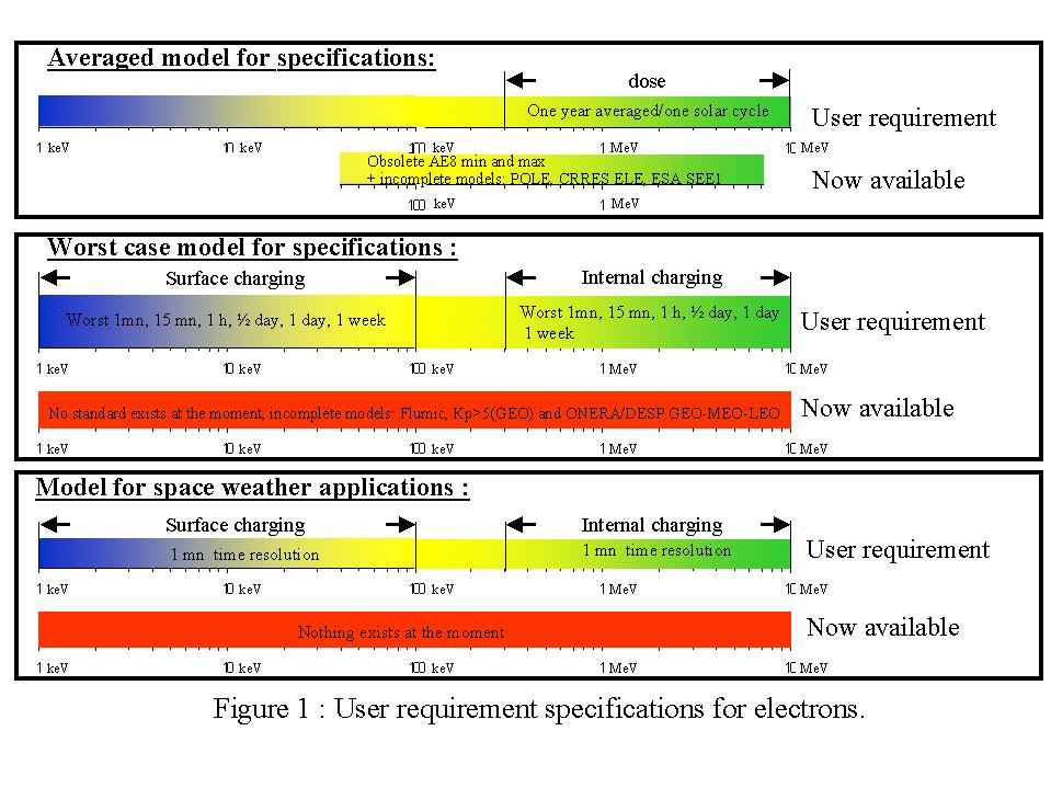
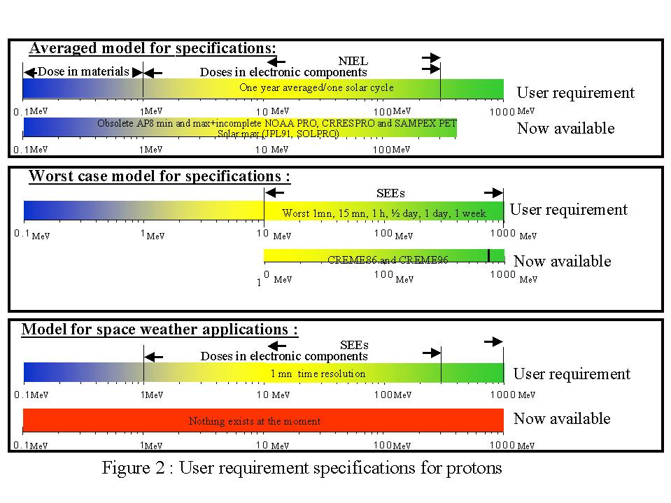
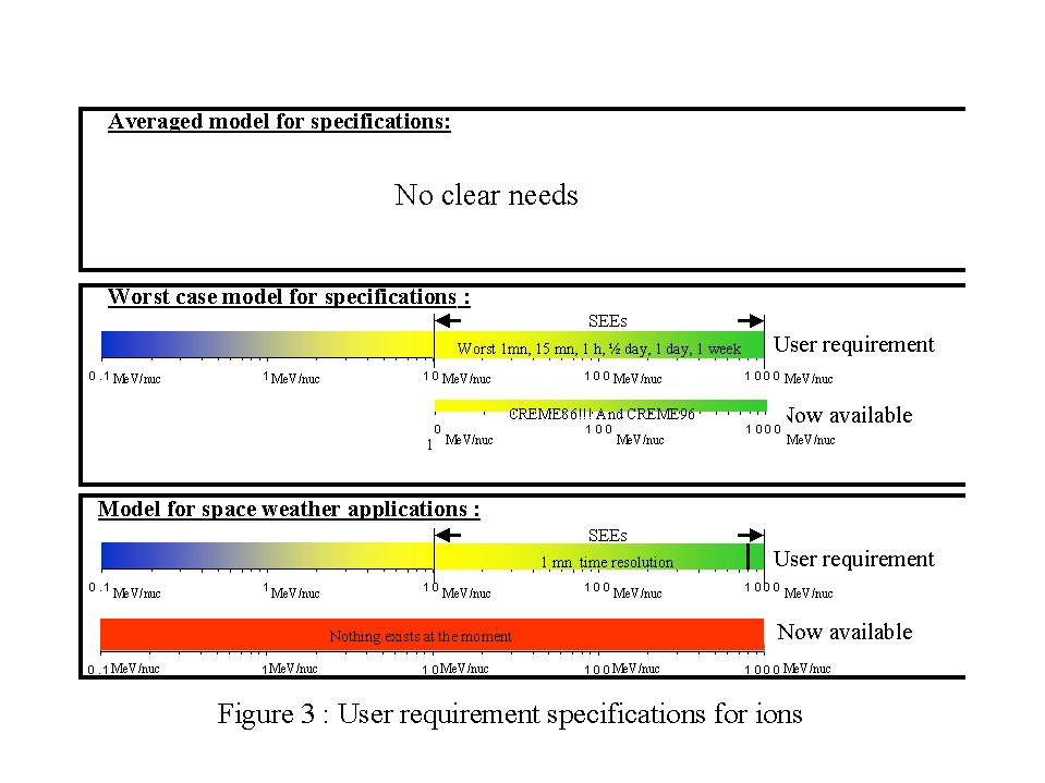
Second a summary of user requirements for "averaged model for specifications", "worst case model for specifications" and "model for space weather applications" is provided in Figure 1 , Figure 2 and Figure 3 depending on particle nature and energy.
|
Satellite anomaly |
Radiative cause |
Satellite effects |
Measurement parameters |
Current practice |
Event location |
Comments |
|
Surface charging resulting in electrostatic discharge |
Accumulation of electrons 0-50 keV |
|
|
|
|
|
|
Internal charging resulting in electrostatic discharge |
Accumulation of electrons 80 keV-3MeV |
|
Same parameters as internal charging |
|
Radiation belts (particularly GEO orbit)
|
|
|
Single event effects |
Protons >10 MeV Ions >10 MeV/nucleon |
|
|
|
High risk during solar particle event
|
|
|
Solar cell degradation due to displacement damage |
0,3-5MeV
8-10MeV |
Reduction in solar cell power |
|
Solar panels designed according to necessary EOL power |
GEO
|
|
Table 1 : Spacecraft anomalies due to ionising radiation in space and their effects on spacecraft (from B. Huet, Alcatel Space, technical note for ESA study 16956/02/NL/LvH.
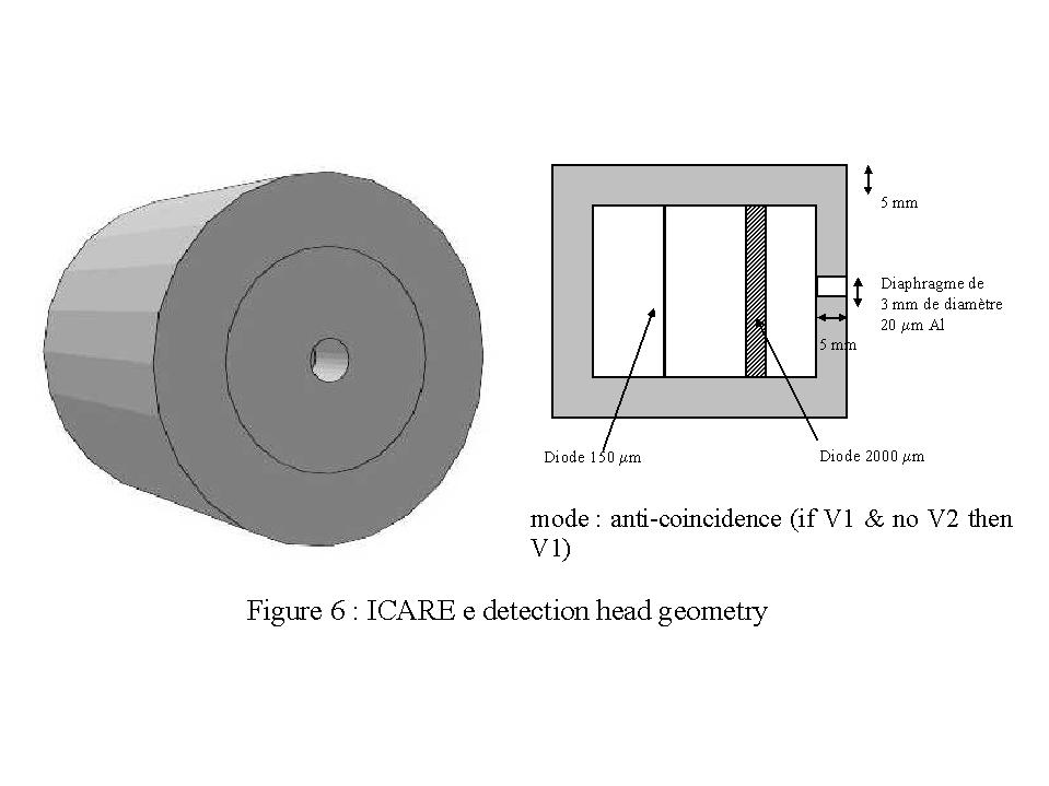
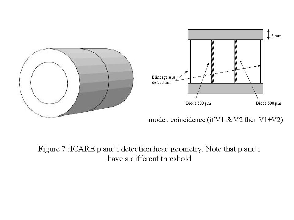
ICARE is composed of a set of three radiation detectors (Figure 4) associated with a component test board (Figure 5). An additional instrument can be added (not part of ICARE) and can be driven by ICARE. ICARE has already flown on board SAC-C spacecraft (http://orbis.conae.gov.ar/sac-c/), starting in December 2000.
The radiation detectors are made of silicon fully depleted solid state detectors used in single and/or coincident and/or anti-coincident mode (Figure 6 and Figure 7). The on-board measurements consist in accumulating energy loss spectra in the junctions over a programmable accumulation period. The spectra are generated through signal amplitude classification using 8 bit ADCs and resulting in 256 channels histograms. The reference levels of the discriminators and gain of the amplifiers are programmable to provide for possible on-board tuning optimization. The accumulation time for the spectra can be programmed from 4 to 256 s.
The species/energy ranges measured are summarised in Table 2 :
|
Specie |
Energy range |
Samples after ground post processing |
Time resolution |
|
Electron |
100 keV-3 MeV |
10 |
4 to 256 seconds |
|
Proton |
5-45 MeV |
7 |
4 to 256 seconds |
|
Helium |
65 MeV and >100MeV |
2 |
4 to 256 seconds |
Table 2 : species/energy ranges measured by ICARE instrument
With such measurements, dose calculations can be assessed as well as internal charging resulting in electrostatic discharge, Single event effects, and Solar cell degradation due to displacement damage (see Table 1). Of course from these measurements, any warning flag customised for the host spacecraft can be generated at ground
The component module functions independently of the detector modes. It is an autonomous sub-module assembled on the main instrument box through 6 screws and consists of two stacked boards that can be switched on or off in each modes. The purpose of this module is to perform real-time testing of advanced devices in order to evaluate their response to high-energy ionizing particles. Both the single event effects and total dose degration are investigated.
The DPCU board provides the essential functions to allow the measurement of single event rates and total dose parametric drifts on the set of devices to be tested (power interface – 7 channels from 3.3 to 5V -, latch-up protection, processor in charge of testing-scheduling-logging, dating....tasks, analog measurement unit .....). The critical applications related with the processor are hardened against radiation via the use of a watch-dog circuitry and a checksum function. The test board houses the devices to be operated and tested for SEE (SEU, SEL, SET...) and total dose (current and offset drifts). Therefore the test module can be adapted from one mission to another i.e. the most sensitive component found on the spacecraft can be implemented on the test board to monitor its sensitivity to the local environment and then provide a warning flag when anomalies are detected. Note that the instrument is also able to function if no module is connected.
In its present version, the test processor is an AD2101 signal processor, single event testing is performed on commercial sub-micronic 4 Mbit SRAMs and 16 to 64 Mbit DRAMs, and total dose degradation is monitored on bipolar and CMOS operational amplifiers and the overall memory plan
A "warning-flag" signal is generated in the following way : each spectrum is divided into 8 groups of 16 channels. Each group of channels is summed and the resulting value is compared to a reference value. If any of the summations exceeds its reference value, the warning-flag is set from 0 to 1. The reference values are programmable and will be a priori preset before launch and can be optimized during the first measurement campaign. The instrument can be programmed into four modes : continuous acquisition mode, single shot acquisition mode, automatic trigger mode and idle. In the third mode, spectra acquisition is automatically triggered if the warning flag switches from 0 to 1. The detectors, acquisition chain and histogram accumulation functions can be switched off independently from the component experiment module.
As the ICARE instrument provides electron, and proton (and He) fluxes in a wide range of energies, it is possible to compute, on demand, any warning flags customized to the host satellite.
Some examples can be provided:
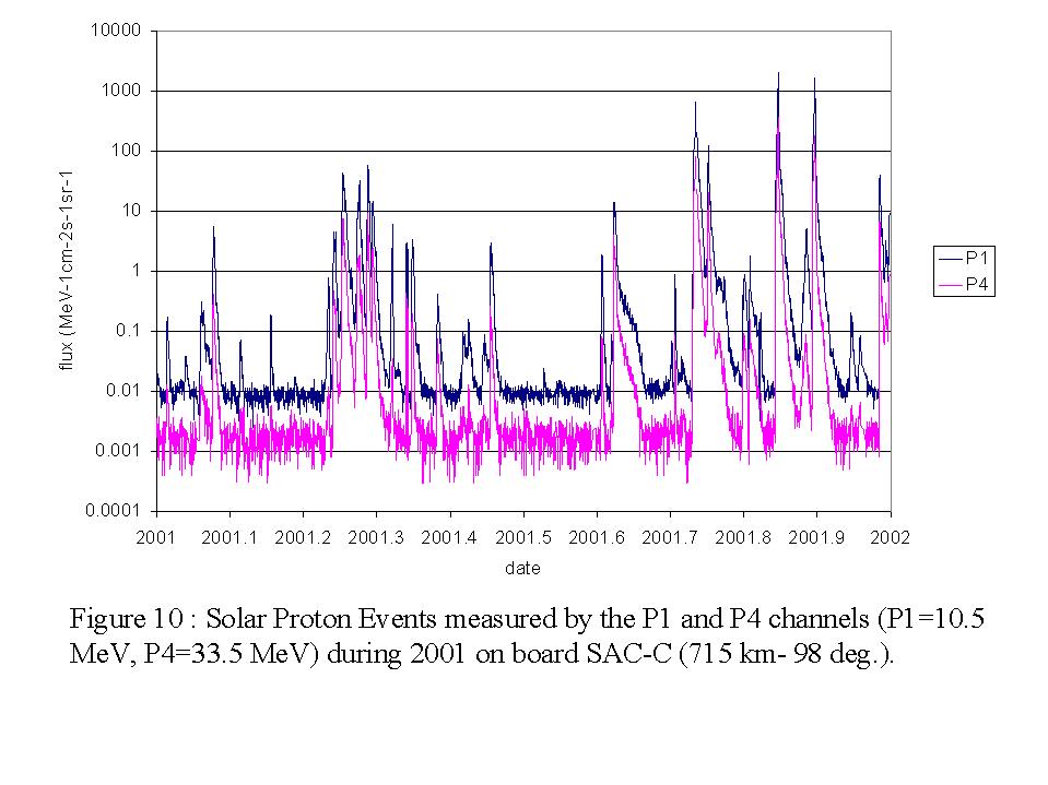
3.5 Example of ICARE measurements from SAC-C mission (LEO)
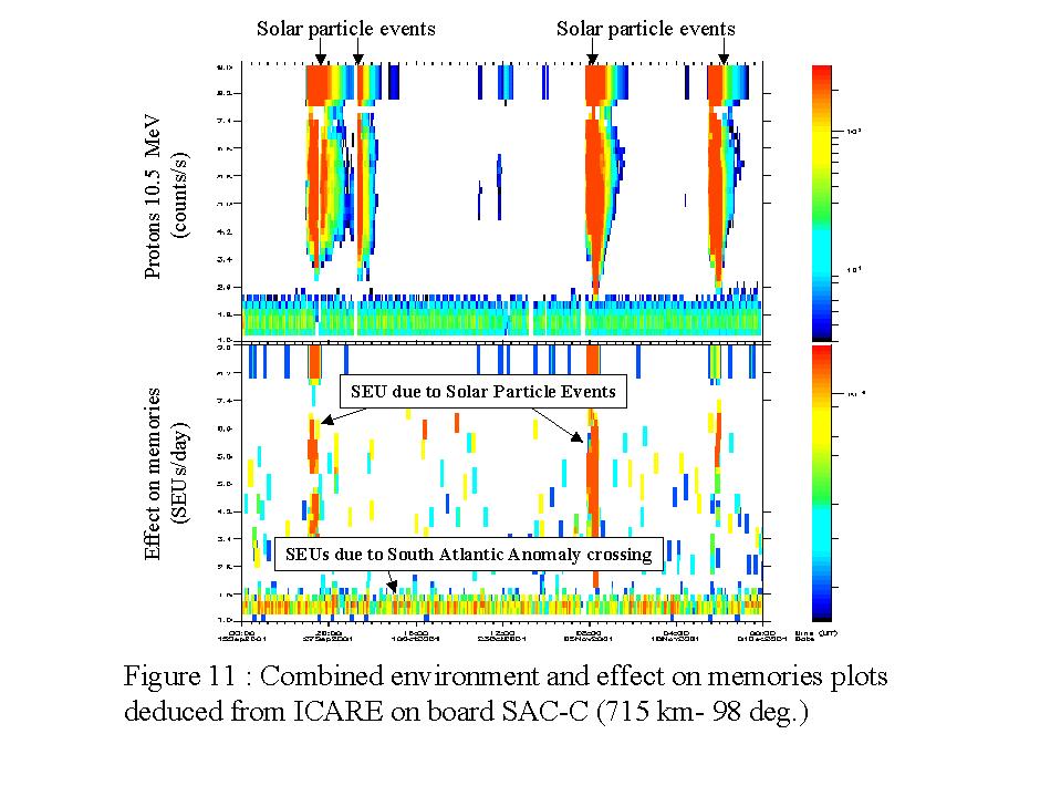
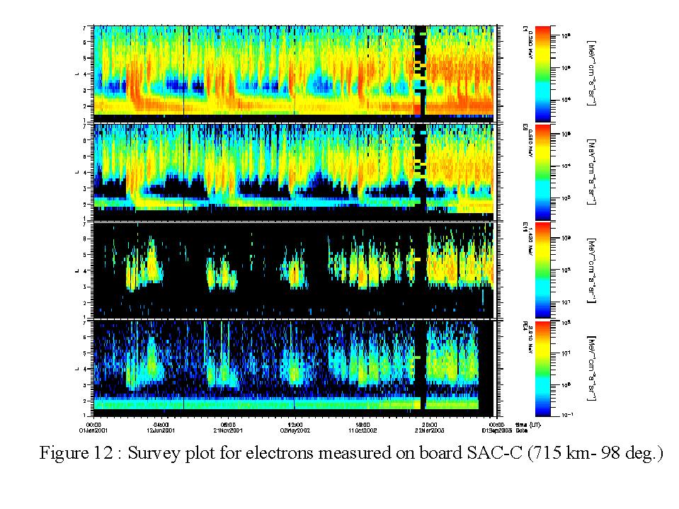
For example, Figure 10 shows the solar proton events measured by two protons channels during the whole year 2001. These measurements were selected only when the spacecraft is at high latitudes, in order to separate accurately solar protons from radiation belt particles. Looking carefully at the data, one can notice the events are not identical at different energies which one expects. Next in Figure 11, proton environment and effects on memories are combined in this time series plot. It can be seen that when solar particles are detected then higher single event upsets (SEU) rates are detected on memories. Finally Figure 12 shows a survey plots of electron measurements, each vertical yellow-red block is for an individual magnetic storm.
ICARE is designed to operate autonomously, without continuous telemetry transmission to the host spacecraft. ICARE always collects raw data from its sensors and prepares all of the data packets at the specified rates. ICARE only transmits the prepared packets upon request from spacecraft. If sufficient telemetry bandwidth is available, data can be continuously read by the spacecraft and transmitted to the ground. This provides the most complete data set. But where telemetry bandwidth is limited, satellite controllers have the option of only requesting data from ICARE when there is some interest. In this alternative, ICARE overwrites its buffer when it is full, i.e. not read.
A set of ground command can be done to modify or customise the way ICARE operates:
5.1.1 Dimensions
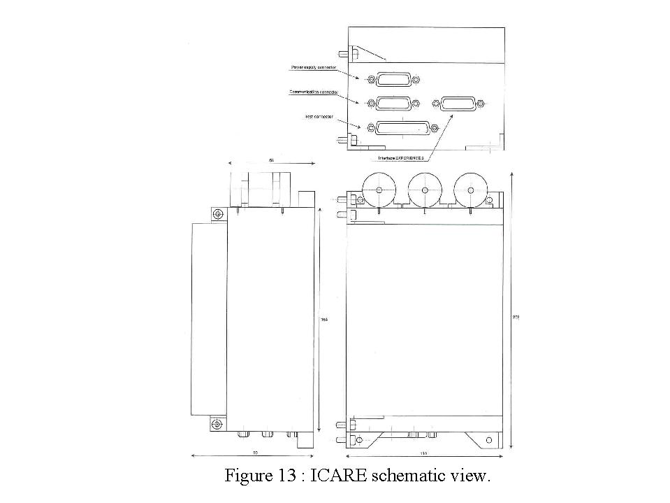
ICARE total dimensions are 116 x 202 x 90 mm (Figure 13).
5.1.2 Mounting and connectors
ICARE is designed to be mounted according to two configurations:
ICARE connectors for power and for signals (command and telemetry) are "SUB D15" type.
5.1.3 Field of view and alignment
ICARE requires a minimal obstruction above telescope apertures. An wide open field-of-view of 90 degree full cone angle centered about the telescopes, normal to the telescope aperture would be optimum. If thermal blankets are to be used, there must be a clear-out area around the telescope apertures.
5.1.4 Mass properties
ICARE mass is 2. Kg
5.1.5 Moving parts
ICARE has no moving parts.
All materials used in ICARE are approved for spaceflight.
ICARE requires 2.5 Watts (peak 2.8 W) nominal operating power with a MIL-STD-1553 interface. Use of RS-422 interface decreases power consumption to approximately 1.5 Watts.
Power supply is actually is the range 20-50 V but can be customise to the host satellite.
The instrument can be power ON or OFF at any time.
5.4 Environmental requirements
5.4.1 Thermal
Thermal cycling test can be done upon request. Then detailed data are provided.
5.4.2 Electromagnetic interference and compatibility
Electromagnetic interference and compatibility test can be done upon request. Then detailed data are provided.
5.4.3 Random vibration
Random vibration test can be done upon request. Then detailed data are provided.
5.4.4 Radiation
ICARE instrument is not rad-hard. The main reason is that the solid state detectors are of course sensitive to radiation and thus have a limited life time (regarding radiative environment). It is not necessary to implement electronic components with a longer life time compared to the one of telescopes.
5.4.5 Other
Non propagation of failure is guaranteed (power and interface).
The maximum size of elementary telemetry is 2.6 Kbytes.
A standard flight display software package (RadShow) has been developed. This software allows the operator to display all of the ICARE data. An example of one of the flight display software screens is shown in Figure 14.
Of course the cost for ICARE monitor depends on the quantity manufactured. The cost for one identification model plus one flight model is on the order of 450 k€. The price includes random vibration, EMC, thermal cycling testing and some help for ICARE integration.
If the component module has to be customised, i.e. redesigned, an over-cost of 100 k€ will be charged.
Once the instrument is operational, ground development will be necessary to extract physical quantities from telemetry:
5 k€ to extract fluxes in an automatic mode from telemetry (spectrometer),
60 k€ to extract component response from telemetry (component module).
For further analysis of the measurements (i.e. developed new specification models …), case by case proposals can be done on demand.
8. Time scale to deliver an unit
Approximate time scale to deliver a unit is one year.